ENR 1.5 HOLDING, APPROACH AND DEPARTURE PROCEDURES
1 General
1.1 UK Holding, Approach and Departure Procedures have been established in accordance with the ICAO Document 8168 (PANS-OPS), except for those UK differences shown at GEN 1.7 and in UK CAA CAP 785 B.
1.2 The UK Instrument Flight Procedures are listed in AD 2.24.
1.3 PANS-OPS vol I and III stresses the need for flight crew and operational personnel to adhere strictly to the published procedures to achieve and maintain an acceptable level of safety in operations.
1.4 Continuous Descent Final Approach ‘CDFA technique’ is the preferred method for non-precision approaches in the UK where practicable.
2 Arriving Flights
2.1
Introduction
2.1.1 Aerodrome specific arrival procedures can be found in the relevant AD 2.22 Flight Procedures and AD 2.24 charts.
2.2
Visual Manoeuvring (Circling) VM(C) in the Vicinity of the Aerodrome after Completing an Instrument Approach
2.2.1 Visual Manoeuvring (Circling) VM(C) is the term used to describe the visual phase of flight, after completing an Instrument Approach, where an aircraft is manoeuvred into position for a landing on a runway which is not suitably located for a straight-in approach.
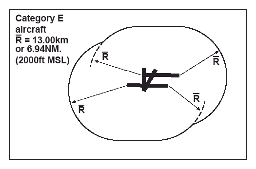
2.2.2 The VM(C) area is the area in which obstacle clearance has been considered for aircraft manoeuvring visually before landing. Aircraft performance has a direct effect on the airspace and visibility needed to perform the circling manoeuvre; since the most significant factor in performance is speed, the size of the VM(C) area varies with the category of the aircraft. The limits of the area applicable to each category of aircraft are defined by combining arcs centred on the threshold of each usable runway; the total area thus enclosed is the VM(C) area - see example at Figure 1.
Figure 1. Construction of Visual Manoeuvring (Circling) Area for a Category E Aircraft

Figure 1. Construction of Visual Manoeuvring (Circling) Area for a Category E Aircraft

2.3
Obstacle Clearance
2.3.1 When the VM(C) area has been established, the Obstacle Clearance Height (OCH) is determined for each category of aircraft. The criteria used to determine the OCH is as follows:
Aircraft Category | Maximum Speeds for Circling (KT) | Circling Area Maximum radii from RWY THR (NM) | Minimum Obstacle Clearance (FT) | Lowest Permissible OCH AAL (FT) |
|---|---|---|---|---|
A | 100 | 1.68 | 300 | 400 |
B | 135 | 2.66 | 300 | 500 |
C | 180 | 4.20 | 400 | 600 |
D | 205 | 5.28 | 400 | 700 |
E | 240 | 6.94 | 500 | 800 |
2.4
Sectorization of Visual Manoeuvring (Circling) Area
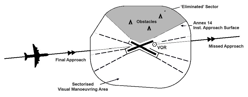
2.4.1 It is permissible to eliminate from obstacle clearance consideration a particular sector, within the total VM(C) area, where the sector lies outside the final approach and missed approach areas; this 'eliminated' sector is determined by the dimensions of the ICAO Annex 14 instrument approach surfaces - see example at Figure 2.

Figure 2. Sectorized Visual Manoeuvring (Circling) Area

2.5
Obstacle Clearance Heights for Aerodromes with Published Instrument Approach Procedures
2.5.1 Visual Manoeuvring (Circling) (VM(C)) OCHs are listed for the total VM(C) area, and where operational advantage can be gained by sectorization, for the relevant sectorized VM(C) area also.
2.5.2 When the principle of sectorization has been applied to a particular aerodrome, two OCA(H) values for VM(C) will be promulgated at AD 2.24. The first OCA(H) will allow a pilot to manoeuvre safely within the total VM(C) area and the second OCA(H) is for the pilot who exercises the option to avoid manoeuvring within the eliminated sector and restricts his visual manoeuvring to the remaining sectorized area.


2.5.3 The OCA(H) for the visual manoeuvring (circling) shall not be less than the OCA(H) calculated for the instrument approach procedure which leads to the circling manoeuvre.
2.6
Summary of Holding and Approach to Land Procedures at Individual Aerodromes
2.6.1 Instrument approach procedures with both precision and non-precision straight in Obstacle Clearance Heights will be heights above the published threshold elevation.
2.6.2 VM(C) Obstacle Clearance Heights will be heights above published aerodrome elevation.
2.6.3 Where the term 'straight ahead' is used in missed approach procedures, pilots should maintain Final Approach Track (FAT) unless a different track is given.
2.6.4 For availability of Instrument Approach Charts, see GEN 3.2.
2.7
Descent Gradient
2.7.1 To permit the approximate rates of descent required in the intermediate and final approach segments of non-precision Instrument Approach Procedures to be calculated, whenever an Intermediate Fix (IF) or Final Approach Fix (FAF) is included in a non-precision procedure, the descent path required in the corresponding approach segment will be specified, as a percentage gradient.
2.8
Procedure Turns
2.8.1 Except where an 80°/260° procedure turn is specifically prescribed, procedure turns specified in instrument approach procedures may be flown as 45°/180° or 80°/260° type, at pilots’ discretion.
2.8.2 Since the 80°/260° procedure turn occupies less airspace along track than the 45°/180° type, aircraft completing an 80°/260° manoeuvre will normally return to the extended Final Approach Track approximately 1 NM closer to the FAP or FAF (when provided) than if a 45°/180° manoeuvre had been used; pilots using an 80°/260° manoeuvre should allow for this factor when preparing for any subsequent inbound descent. Where an 80°/260° procedure turn is specifically prescribed, due allowance for this factor will already be provided in the procedure design.
2.9
Race-track Procedure
2.9.1 Extensions to holding patterns may be specified in some cases as alternative procedures for use after holding. Where such alternative procedures are joined without first entering the hold, they should be joined and flown as race-track procedures. However, because of the requirement to intercept the inbound track before returning to the facility following a Sector 1 parallel entry in such procedures, and its effect on the distance available for any subsequent descent, aircraft joining a race-track procedure from Sector 1 are recommended to join the hold prior to entering the racetrack.
2.10
Established
2.10.1 Aircraft are considered to be 'established' when they are within half full-scale deflection for the ILS and VOR, or within ± 5° of the required bearing for NDB(L).
2.11
Missed Approach Climb Gradient
2.11.1 Unless otherwise specified, the normal climb gradient upon which Missed Approach Procedures are based is 2.5% (1 in 40).
2.11.2 Where an operational advantage can be gained from an increased missed approach climb gradient, an additional OCA(H) associated with the increased missed approach climb gradient will also be published.
2.12
Radar Approach Procedures
2.12.1 During the Intermediate phase of the procedure the pilot will be asked to check both his Minima and the Missed Approach Point (MAPt); he will not be given the OCA(H) for his category of aircraft nor the location of the MAPt unless he specifically requests this information.
2.12.2 SRA procedures designed to ICAO PANS-OPS criteria permit descent on final approach to the OCA(H) (subject to any specified height/distance (Step Down Fix (SDF) limitation), without regard to the 'advisory altitudes/ heights' given by the Controller. These 'advisory altitude/heights' are not essential for obstacle clearance and are only provided as a guide to pilots wishing to maintain a constant angle descent path.
2.12.3 Pilots flying an SRA requiring the alternative datum profile, will be passed advisory altitudes/heights based on the appropriate datum and rounded up to the nearest 10 FT.
2.12.4 Pilots are recommended to fly to the radar advisory altitude/heights. However, where an SDF is specified as part of the procedure the SDF 'not-below' altitude/height is mandatory. Adherence to the nominal descent gradient defined by advisory altitude/ heights will ensure compliance with SDF minimum altitude/height requirements.
2.12.5 A MAPt is designated for each procedure; it is normally located at the point where the radar approach terminates (Radar Termination Range (RTR)). However, where operationally advantageous, the MAPt for the 2 NM SRA may be designated as 1 NM after RTR (i.e., 1 NM before touch down zone).
Note: Where the MAPt is designated as 1 NM after RTR, talkdown will still cease at 2 NM (RTR), and it will be the pilot’s responsibility to determine when the MAPt has been reached.
3 Departing Flights
3.1 Aerodrome specific departure procedures can be found in the relevant AD 2.21 Noise Abatement Procedures, AD 2.22 Flight Procedures and AD 2.24 charts.
4 Other Relevant Information and Procedures
4.1
FM Broadcast Interference
4.1.1 Aircraft ILS/VOR equipment may experience interference from high powered FM broadcast stations in the radio frequency band 88 - 108 MHz (GEN 3.4 refers). Pilots are warned that instrument approach procedures based on ILS/VOR may not be available.
4.2
Protection of Instrument Approach Procedures at Aerodromes outside Controlled Airspace
4.2.1 Aerodromes located outside Controlled Airspace, for which Instrument Approach Procedures (IAP) are published, are identified by a 'feathered arrow' symbol on the Aeronautical Charts ICAO Scale 1: 500 000 United Kingdom and the Topographical Air Charts of the United Kingdom Scale 1: 250 000. Portrayal on these charts is provided to assist pilots of VFR flights to avoid confliction with IFR traffic at these aerodromes. Pilots are urged to take this information into account in their pre-flight planning.


4.2.2 For further information relating to Air Traffic Services at Aerodromes outside Controlled Airspace, please refer to GEN 3.3 Air Traffic Services.